DBB VS DIB Ball Valve
DBB ball valve is the common requested, while DIB ball valve is requested for unique application and media, and various environmental challenges where critical isolation is needed to ensure that leakage does not occur such as LNG, petrochemical,transmission and storage.
What are DBB and DIB Valves?
DBB-Double block and bleed valve
API 6D definition:
"Valve with two or more seating surfaces that, in the closed position, provides a seal against pressure from both ends of the valve with a means of venting/bleeding the cavity between the seating surfaces."
The DBB feature of the valve or valves is the ability to segregate two pressure sources and to bleed or vent pressure in the void between the two sealing elements (blocks). The bleed may be in the pipework or pipeline when two valves are used or in the valve body between the two seats when the valve has the DBB feature.
DIB-Double isolation and bleed valve
API 6D definition:
"Valve with two or more seating surfaces, each of which, in the closed position, provides a seal against pressure from a single source, with a means of venting/bleeding the cavity between the seating surfaces."
The DIB feature of the valve or valves is the ability to provide two sealing elements to a single pressure source and to bleed or vent between the two sealing elements.
There are two options:
DIB-1: Double Piston Seat x Double Piston Seat
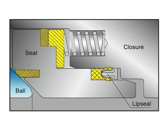
In a DIB-1 design, both seats are of Double Piston Effect (DPE).
Pressure acts on both sides of the seat to create a tight seal. In the event of damage to one seat, the pressure in the body cavity activates the opposite seat to seal. Depending on the service application, this design may require installation of a Liquid Relief Kit (LRK) to relieve excess pressure developed in the body cavity of the valve due to thermal expansion.
DIB-2: Double Piston Seat x Single Piston Seat
In a DIB-2 design, two types of seats are utilized – Double Piston Effect (DPE) and Single Piston Effect (SPE). This feature allows the DPE seat on one side of the valve to provide a positive seal in either direction, while the SPE seat on the other side of the valve allows for relief of excess pressure within the valve body cavity to the upstream or downstream side of the valve, depending on orientation.
This design eliminates the need for Liquid Relief Kit(LRK)installation.
To assist with orientation concerns during installation, Relia provides extra labeling and nomenclature on the valve body to identify which seat is self-relieving.
DBB, DIB Ball Valve Comparation
| Seat Construction Type |
Seat Position | Installation direction Requirement |
Seat seal for fluid directions |
Figure No. | |
| Upstream valve seat | Downstream valve seat | ||||
| DBB | Single piston effect seat (undirectional sealing seat) | Single piston effect seat (undirectional sealing seat) | No | 2 | Fig. 1 |
| DIB-1 | Double piston effect seat (bidirectional sealing seat) |
Double piston effect seat (bidirectional sealing seat) |
No | 4 | Fig. 2 |
| DIB-2 | Single piston effect seat (undirectional sealing seat) |
Double piston effect seat (bidirectional sealing seat) |
Yes | 3 | Fig. 3 |
| Double piston effect seat (bidirectional sealing seat) |
Single piston effect seat (undirectional sealing seat) |
Yes | 3 | Fig. 3 | |
DBB, DIB Ball Valve Diagram
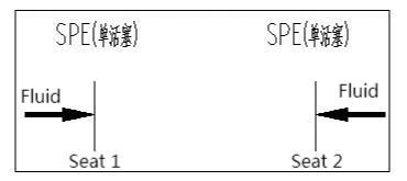
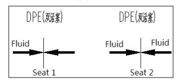
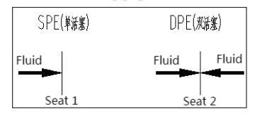
Fig. 1: DBB Ball Valve
Fig. 2: DIB-1 Ball Valve
Fig. 3: DIB-2 Ball Valve
Isolation Valve Types
| Valve Type | Sealing Arrangement | Block and Bleed | Double Block and Bleed | Double Isolation and Bleed |
|
| Block Valve | Two Valves with Bleed Between | Any valves with bidirectional sealing | Yes | Yes | Yes |
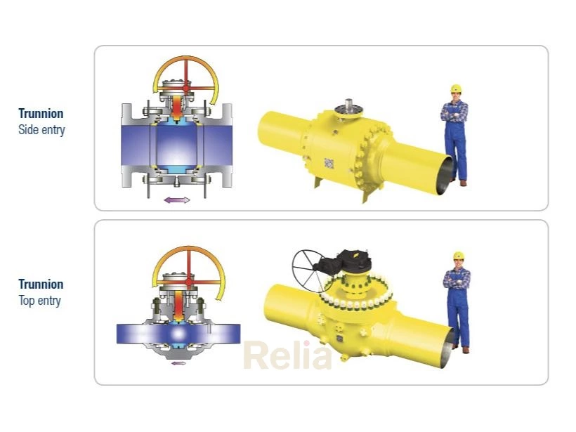
| Trunnion Mounted Ball Valve | Upstream sealing, pressureenergized, self-relieving (Note1) |
Yes | (Note 4) | No(Note 5) | |
| Trunnion Mounted Ball Valve DIB-1 | Upstream and downstream sealing,pressure energized, example, two bidirectional sealing seats (Note1) | Yes | (Note 4) | (Note 6) | |
| Trunnion Mounted Ball Valve DIB-2 | Upstream and downstream sealing,pressure energized, example, one bidirectional and one unidirectional sealing seat (Note1) | Yes | (Note 4) | Only if bidirectional seatis on downstreamside (Note 6) |
|
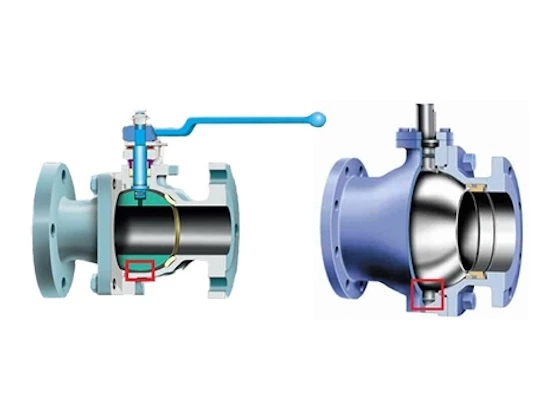
| Floating Ball Valve | Pressure energized | No(Note 2) | No | No | |
| Gate Valve | Slab and/or Through-conduit | Pressure energized—downstream sealing only/fixed seats (Note1) | No(Note 2) | No | No |
| Slab and/or Through-conduit DIB-1 | Pressure energized—upstream and downstream sealing (Note1) | Yes | Yes (Note 3) |
Yes(Note 3) | |
| Expanding DIB-2 | Mechanically energized | Yes | Yes (Note 3) |
Yes (Note 3) | |
| Plug Valve | Standard | Pressure energized,downstream sealing | No(Note 2) | No | No |
| Expanding DIB-1 | Mechanically energized | Yes | Yes | Yes | |
FOOTNOTES
NOTE 1 The terms “ upstream” and “ downstream” refer to the pressure source and open end/equipment respectively and do not refer to flow direction
NOTE 2 Not possible to bleed from valve body, but bleed may be in downstream pipework/pipeline
NOTE 3 Depending on detail design of the valve, some valves may have preferred sealing direction and/or a specified sequence of operation
NOTE 4 Depending on detailed design
NOTE 5 Downstream seat may provide a second barrier at pressures below the cavity relieving pressure barrier
NOTE 6 Depending on detailed design and ability to achieve testing per L.14, L15, L.16 or L.18
How to Test DBB, DIB Ball Valve
DBB Ball Valve Test
The purchaser shall specify when double block and bleed (DBB) valves shall undergo additional testing. The testing shall be performed as follows:
— With the valve unseated and partially open, the valve and its cavity shall be filled with test fluid.
— The valve shall then be closed, and the valve body vent valve opened to allow excess test fluid to overflow from the valve-cavity test connection.
— The test pressure shall be applied simultaneously from both valve ends.
— Seat tightness shall be monitored via overflow through the valve cavity connection.
— Acceptance criteria shall be per the requirements of 10.4.3. Except for the metal-to-metal seat test, the leakage rate shall not be more than two times ISO 5208, Rate C.
DIB-1 Ball Valve Test
The purchaser shall specify when each seat in a double isolation and bleed (DIB-1) valve shall be tested in both directions. The testing shall be performed as follows:
— Cavity-relief valves shall be removed if fitted.
— The valve and cavity shall be filled with test fluid, with the valve unseated and partially open, until the test fluid overflows through the cavity relief connectors.
— To test for seat leakage in the direction of the cavity, the valve shall be closed.
— The test pressure shall be applied successively to each valve end to test each seat separately from the upstream side. Leakage shall be monitored via the valve cavity pressure relief connectors.
— Thereafter, each seat shall be tested as a downstream seat. Both ends of the valve shall have the ends open to the atmosphere, and the valve cavity shall be filled with test fluid.
— Pressure shall then be applied while monitoring leakage through each seat at both ends of the valve.
NOTE Some valve types can require the balancing of the upstream and valve cavity pressure during the downstream seat test, in which case only one end of the valve shall be open to the atmosphere.
— Acceptance criteria shall be per the requirements of 10.4.3 of API 6D. Except for the metal-to-metal seat test, the leakage rate shall not be more than two times ISO 5208, Rate C.
DIB-2 Ball Valve Test
The purchaser shall specify when the bidirectional seat in a double isolation and bleed (DIB-2) valve shall be tested in both directions. The testing shall be performed as follows:
— Cavity-relief valves shall be removed if fitted.
— The valve and cavity shall be filled with test fluid, with the valve unseated and partially half-open, until the test fluid overflows through the cavity relief connectors.
— To test for seat leakage in the direction of the cavity, the valve shall be closed.
— The test pressure shall be applied successively to each valve end to test each seat separately from the upstream side. Leakage shall be monitored via the valve-cavity pressure relief connectors.
— To test the bidirectional seat from the cavity test, pressure shall be applied simultaneously to the valve cavity and upstream end. Monitor leakage at the downstream end of the valve.
— Acceptance criteria shall be per the requirements of 10.4.3 of API 6D. Except for the metal-to-metal seat test, the leakage rate shall not be more than two times ISO 5208, Rate C.